Problem Statement
-
Over 600,000 cardiac medical devices recalled from 1990-2000.
40% of recent recalls were due to software issues
It is essential to guarantee the safety and efficacy of the device software

-
The Pacemaker (and other medical devices):
- Autonomous device with minimum human interaction, therefore has to be able to operate under all possible conditions.
- Limited diagnostic capability, inevitably leading to false-positives and false-negatives, and limited therapy capability, being able to treat the disease to a certain degree.
- It is the safety of the patient we care about. Therefore the safety of the pacemaker must be evaluated in closed-loop within its environment
-
The physical plant:
- Not only the heart, but also the rest of the body
- Different dynamics even in a single patient
- Each condition has its own corresponding optimal condition
-
The final product: The safety and efficacy of the device itself
-
The development process: Rigorous design process which provides traceability of requirements
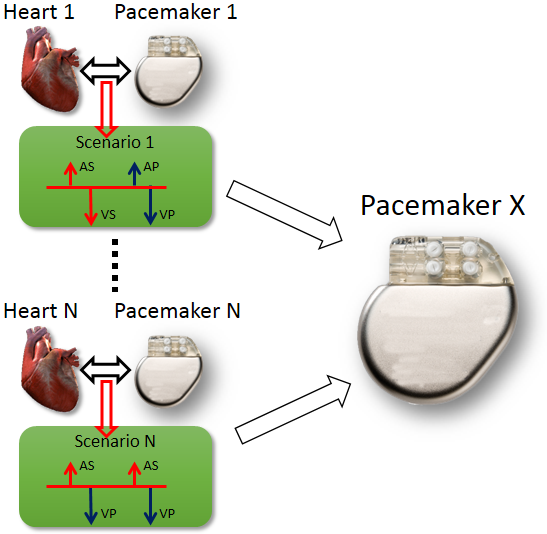
During the past decades, pacemakers implanted into patients have recorded episodes of closed-loop interactions (Senario 1 ~ Senario N) between the heart in different conditions (Heart 1 ~ Heart N) and the pacemaker . The recordings are either appropriate pacemaker behavior in response to heart condition which all new pacemakers should also have, or inappropriate pacemaker behavior so that the new pacemakers should avoid. In order to evaluate the performance of a new pacemaker design (Pacemaker X), the inputs from the hearts in those recordings, representing different heart conditions, are fed into the new pacemaker and the outputs of the new pacemaker are compared to the recorded outputs in those senarios.
The problem of open-loop testing is that the input signals from heart do not capture the heart physiology and will not change to different pacemaker outputs. Given a closed-loop interaction between Heart i and Pacemaker i and feed its heart input signals to Pacemaker X will not capture the closed-loop behavior of Pacemaker X under heart condition i. In order to evaluate pacemaker executions under different heart conditions, especially the executions with adquate depth, there has to be a model of the heart which can capture the physiological conditions of the heart and respond to pacemaker outputs.
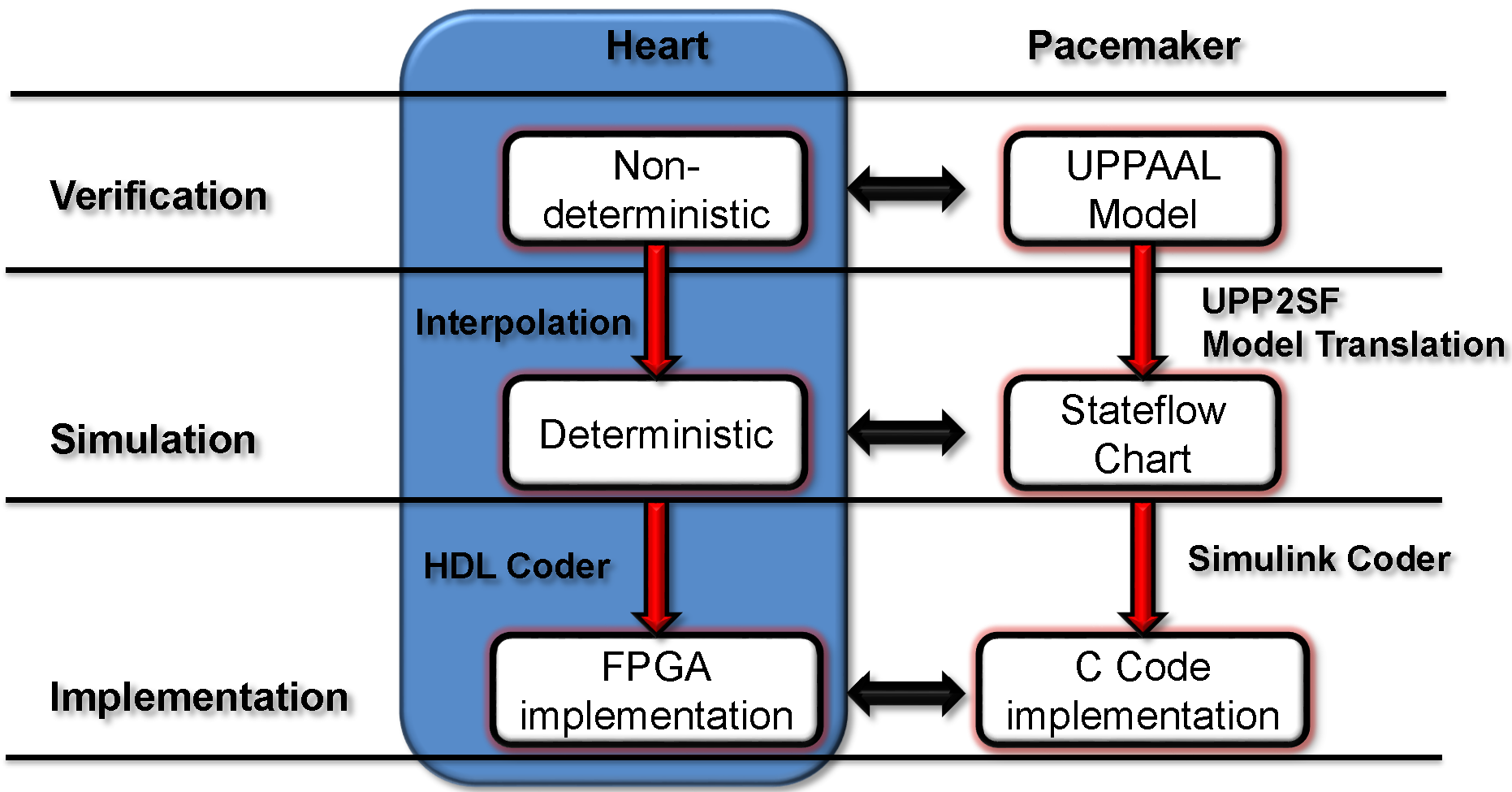
We developed a model-based design framework for pacemaker software. A heart model structure was designed based on the electrophysiology of the heart. At each development stage a version of the heart model is available to interact with the pacemaker model/implementation.
- At verification level we have a set of non-deterministic version of our heart models with different abstraction level which covers all possible inputs to the pacemaker under different heart conditions. Depending on the condition of the safety/efficacy properties, we choose heart model with appropirate structure and abstraction level to cover the inputs to the pacemaker under heart conditions specified in the properties.
- At Simulation level the non-determinism of our heart model are resolved by linear interpolation of the parameter ranges. The deterministic version of our heart model responds to pacemaker pacing signals the same way as a real heart.
- The deterministic heart model can be translated into HDL code by Mathworks HDL coder and implemented on a FPGA chip. With appropriate analog interface, the platform can be used for closed-loop testing of pacemaker implementations.
Heart Basics
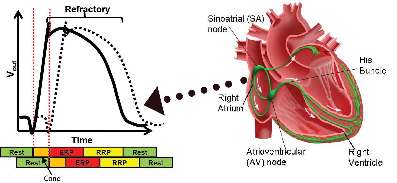
The coordinated contraction of the heart muscles are governed by the electrical conduction system. The Sinoatrial (SA) node, which is the natual pacemaker, periodically generates electrical impulses that conduct along the electrical conduction system, triggering muscle contractions. Anormalies in the generation and/or conduction of the electrical signals will result in irregular heart rhythms, which are referred to as arrthymia.
When a heart tissue encounters a voltage change, it discharges the ions inside, causing voltage change outside the tissue. The behavior is referred to as depolarization. The figure on the left illustrates the voltage changes over time (Action Potential) outside a heart tissue (solid line) and its nearby tissue (dashed line). After the outside voltage reaches a certain threshold after some time, the tissue nearby is also depolarized. This domino effect continues so the initial depolarization from the SA node can travel through the whole heart. After the depolarization the tissue needs time to recharge, as we can see the voltage gradually drop back to its resting value. This recharging period is referred to as the Refractory period during which new depolarization will be inhibited or triggering deformed action potential. The colored bar below shows the corresponding timing periods. More information can be found in this quick tutorial.
Heart Modeling
We chose Timed Automata as the formalism for the heart model for several reasons:
-
Nondeterminism which enables model abstraction which increase coverage.
- The reachability problem for timed automata is decidable, allowing us to explore the whole state space of the heart and pacemaker.
- Most timing behaviors of the heart can be captured by timed automata
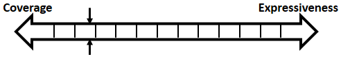
In order to be used in different stages during the development process, the structure and parameters of our heart model need to be adjusted to balance between Coverage vs. Expressiveness.
Intuitively, the more complex the model is, there is more constraints on its behaviors, thus limiting its coverage. On the other hand, the added complexity allows us to capture more detailed mechanisms of the heart, allowing us to precisely model a specific heart condition. So instead of developing a single heart model, we developed a series of heart models at different abstraction levels. With Counter-Example-Guided Abstraction & Refinement (CEGAR) framework, we are able to choose the proper level of heart model abstraction during verification thus balancing coverage and expressiveness.
For evaluating pacemaker which has only two leads and do simple thresholding for signal processing, we developed heart models at different abstraction levels, where each abstraction covers all possible states of the model in the previous abstraction level. Each abstraction step reduces the complexity of the timed automata component and/or the structure of the whole model. This establishes a timed simulation relationship between abstraction levels with  where n=[1,4]. More details on heart model abstraction can be found in our STTT paper.
Behaviorial Model of Heart Tissue
We first start with modeling the electrical behaviors of a heart tissue. A whole model of the heart consists of node automata (N0) which models the timed transitions among different time periods with different behaviors after the tissue is depolarized. The heart can then be modeled as:  where N can be arbitarily large.
Proposed use:
- Study complex and chaotic heart conditions like Atrial Fibrillation.
- Creating spatial and temporal map of the heart during Electrophysiology Studies
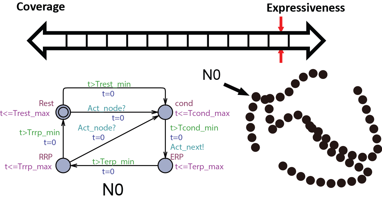
Abstract conduction delay with paths
In this abstraction we replace the cond state of N0 with path automata. The heart model H0 can be replaced by  . A more general abstraction abstracts 3 nodes and 2 paths into 2 nodes and 1 path:
 . With this property we can further abstract the structure of the model. The heart model H0.5 can be further abstracted into
  where m=9 in the structure shown on the right.
Proposed use:
- Study heart conditions with additional pathways including reentry circuits.
- Patient-specific heart model for general Electrophysiology Study.
Merging equivalent states
 At this abstraction level, we merge the RRP state with the Rest state in the node automata and Double with the Idle state in the path automata due to the same behavior. We also further abstract the structure of the heart model so H1 can be abstracted with
  . The AV node has very large ERP period thus cannot be abstracted away.
Proposed use:
Verify pacemaker algorithms in which the blocking property of the AV node cannot be ignored
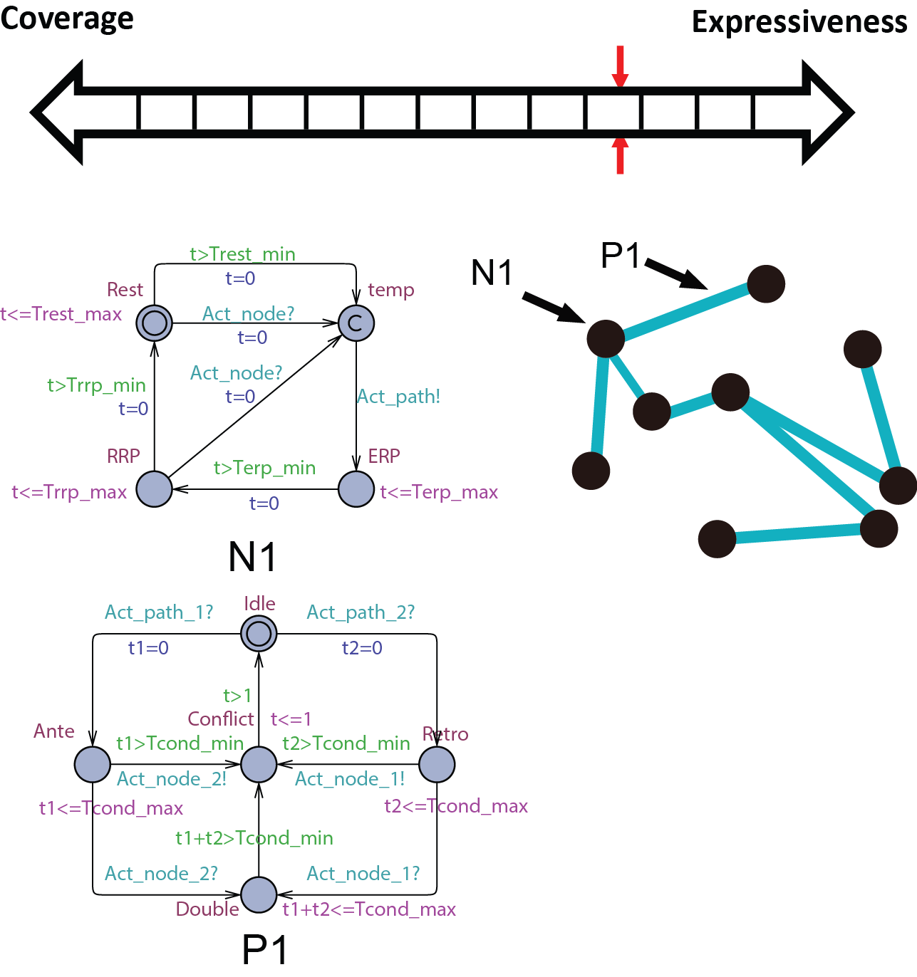
Replacing the blocking property of ERP with non-determinism
 The node automata do not trigger path conduction in response to external activation during its ERP state. In this abstraction level, this function is replaced by a non-determnistic transition in the path automata, as shown in the figure on the right. As a result of the abstraction, the AV node can be abstracted away and the heart model H2 can be abstracted by
  .
.
Proposed use:
Verify pacemaker algorithms in which A-V conduction cannot be ignored
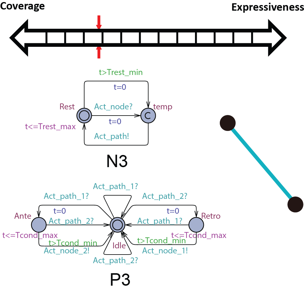
Abstracting the conduction property with non-determinism
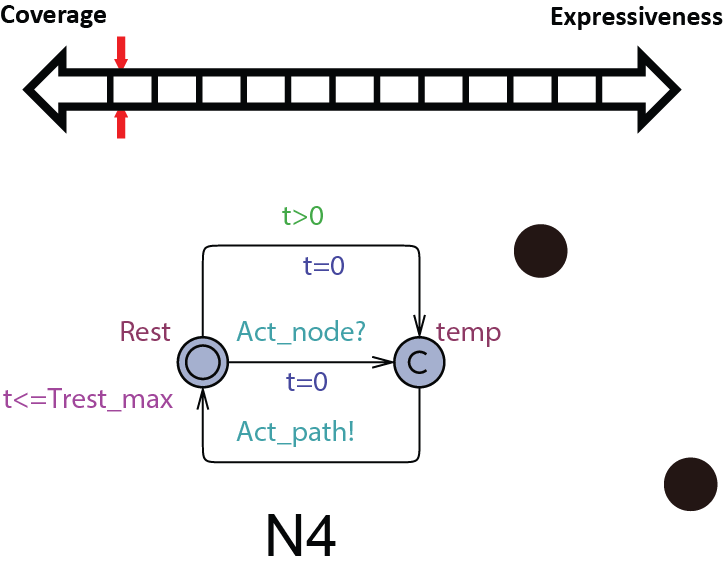 Since the pacemaker only has two leads, the structure of the heart model can be further reduced to two node automata which can generate inputs to the pacemaker without timing constraints. The heart model H3 can be further abstracted to
  . This heart model covers all possible inputs to the pacemaker and is our most abstracted model.
Proposed use:
Verify pacemaker algorithms with unconditional properties.
Heart Model Simulation & Implementation
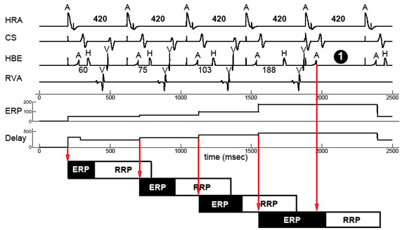 For simulation the heart model has to be deterministic. We resolve the non-determinism in our heart models with linear interpolation. The ERP period of the node automata and the conduction delay of the path automata are determined by the state of the node automata when it was activated. In this way we are able to simulate progressive heart behaviors like the Wenckebach A-V block which is shown on the right. More details on the linear interpolation can be found in our VHM proceeding paper.
 Pacemaker has two leads placed against the inner heart wall. Each lead has two electodes which can sense the electrical voltage changes near the heart tissue. The depolarizations of the heart tissue travel across the heart like a wave. Clinical studies shows that the depolarization wave move toward and away from the electrode, the voltage sensed by the electrode increases and decreases correspondingly.
We model this behavior by calculating the distance between the location of the depolarization wave within the path automata, and the location of the electrode. The animation on the right shows the simulated voltage sensed by two electrodes (Uni1,Uni2). The left column shows the analog signal sensed by the two electrodes and their difference. The right column shows the logical pulses that the pacemaker gets after simple thersholding.
With the model of the electrodes we are able to put imaginary electrodes at different places of our heart model. This also allows us to simulate behaviors like pacemaker lead dislodge and crosstalk. More information on these subjects can be found in our EMBC'11 paper

We created an user interface in Matlab so the user can create a heart model, interact with it and visualize the simulation.
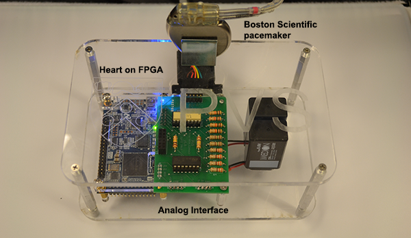
The heart models created in the user interface can be automatically generated into executable files and run on a hardware platform. The first version of the Heart On a Chip platform uses a FPGA board to run the heart model. Through an analog interface circuit the heart model can interact with a real pacemaker. This platform enables us to do closed-loop testing on a pacemaker implementation with different heart conditions. More details on the platform can be found on this website and our technical report.
The second generation Heart On a Chip will be on a microcontroller with easier configuration and richer interface. The platform will be provided to the research community with low cost. Information on how to get access to the platform is coming soon.